Replicating a physical part¶
You have the part in your hand: a broken clip, a wall plate, a knob, a bracket from an appliance. Usually it was injection molded. You want a printed one that does the same job. That is not the same as copying its shape: a molded part is designed around the mold (draft, thin even walls, coring, ribs, a living hinge in polypropylene), and a print is better without most of that. What must stay the same is what it fits: the holes, their spacing, the faces that touch something else.
So replicating is three jobs:
- Measure the right things, well: every size that fits something, from one datum, three times; the rest only as well as the look needs.
- Decide, for each dimension, whether it must match (critical) or may change (free), and what to do with each molded feature.
- Keep the record (the replication spec) and check the model against it.
The MCP prompt replicate_part walks an assistant through all of it, with two stops for
your confirmation: after the measurement plan, and after the list of changes. The record is the
part's MEASURE.md (the measurement sheet with
four more columns), and the replication_spec tool checks the script's Dims against it.
If you also have a 3D scan of the part, it helps with the shape; it is used the way a remix uses a downloaded mesh, but calipers win for every size that fits something.
How a session goes¶
- Identify. You describe the part, what it mates with and how (screws, a snap, a press fit,
a seal), and attach photos or a drawing. The assistant names how it was made (molded parts
show draft, a parting line, round ejector-pin marks, a gate) and asks what it cannot see:
the mating parts, the material (look for a recycling mark such as
>PP<or>ABS<molded inside), heat, sunlight, how often it comes apart. - Measurement plan (stop). The assistant writes
MEASURE.mdwith one row per dimension, the values empty: the feature, its class, the tool and method, the accuracy you need, the Dims field it will become, and the photos to take. You measure and fill it in. - Classify and decide (stop). The assistant reads your readings back, points out readings that disagree (a tapered wall, an oval hole), and proposes what to do with each molded feature, each with its reason in the Why changed column; plus the material, the print orientation and the fits. You confirm.
- Model. Every dimension becomes a named
Dimsfield; critical ones as measured, or with the reason they differ (a clearance, a standard size). - Verify. The usual checks, then
replication_specuntil it has no warnings,measureon the critical features of the built part, and a fit-test template of each critical interface before the full print.
The measurement plan¶
The measuring guide has the methods: calipers (outside, inside, depth, step), gauges, tracing, offsets, photos with a scale. For a part you are copying, the plan adds:
- One datum for everything (the centre of the main hole pattern, a flat back, a mating face), and hole spacings measured edge to edge (outside of both and inside of both, averaged) rather than chained.
- Three readings of every critical size, at slightly different places, all three in the
Value cell:
4.21, 4.19, 4.22. The spec averages them and warns when they spread wider than the accuracy you wrote. - Where on a molded wall you measured. Molded walls taper (draft), so a wall or a boss reads differently at its root and at its tip. Measure where it mates, or at mid-height, and say so.
- Threads with a thread pitch gauge and calipers on the outside diameter; metric and inch sizes look alike (M3 and 4-40, M6 and 1/4-20).
- Standard sizes (a screw clearance hole, NEMA box screw spacing, a bearing seat) get the
source
standardwith the standard's name, and are still checked against the part. - Photos: an overview, each critical feature square on with a scale in its plane, the back (coring, ribs, bosses) and any marking.
Critical or free¶
Each row of the spec has a Class:
| Critical: must match | Free: may change to print better |
|---|---|
| mating interfaces: faces that sit against something | outer styling, the look of the outside |
| hole sizes and hole spacings; slots that take a screw | ribs, gussets, coring |
| fits: press, sliding, free (with the clearance from your settings) | wall thickness away from the interfaces |
| sealing and bearing faces | fillets and chamfers that touch nothing |
| snap and latch geometry: the hook, the catch, its travel | text, logos, texture |
| threads (size, pitch, length of engagement) | features for other variants of the product (extra bosses, knock-outs) |
| the envelope where it fits into or against something | the overall size where nothing constrains it |
When in doubt, the assistant asks; "it fits into this recess" makes the outline critical.
Molded features and what to do with them¶
A molded part carries features that exist for the mold, not for the job. The prompt proposes what to do with each, and the reason goes in the spec's Why changed column. The rules (C1–C12) and their sources are in BEST_PRACTICES §19.
| Molded feature | Why the mold has it | In the printed copy | Rule |
|---|---|---|---|
| Draft (faces taper along the mold's opening; molded 0.5–2°, more under texture) | so the part releases | remove it; keep a taper only where it does a job (a taper fit, parts that nest or stack) or is part of the look. Measure a drafted wall where it mates, or at mid-height, and say which | C1, C2 |
| Thin even walls, coring (molded walls ~2–4 mm, thick areas hollowed) | to fill and cool evenly without sink | solid, or thicker walls in whole line widths; keep a cored pocket only where it does a job (weight, clearance, a mating feature) | C3 |
| Ribs and gussets (molded 40–60 % of the wall) | stiffness without sink | keep where they run (the stiffening intent) at full wall thickness, or drop them where solid replaces them | C4 |
| Sink marks, parting line and flash, ejector-pin marks, gate vestige, knit lines | marks of the molding | never model them or measure on them; a sink shows a thick section behind it; a crack on a knit line is a molding weakness | C5 |
| Living hinge (PP or PE, 0.2–0.35 mm, a million cycles) | PP flexes for ever | cannot be copied: 0.4–0.6 mm in nylon, TPU or PP with the hinge width along Z (tens of cycles), or a pin or print-in-place hinge | C6 |
| Snap fit (sized for POM, PP, nylon) | molded resins take high strain | recompute the arm for the print material's strain (the snap_arm recipe), print it flat, ~60 % of the strain for snaps opened often | C7 |
| Screw bosses, self-tapping holes, molded threads, inserts | sized for sink and molding | the position and the screw, not the molded proportions: thicker wall and gussets; a heat-set insert or nut for screws taken out often; threads modeled only at M5–M6 and up; declare the screw as hardware | C8 |
| Material (PP, POM, PA, ABS, PC) | chosen for strain, heat, creep, chemicals or sunlight | pick the print material by that property: strain or a hinge → PETG, nylon, TPU or a redesign; heat → ASA, PC, PA (PLA softens near 55–60 °C, molded PP ~80–85, POM ~110); outdoors → ASA; sliding → nylon. The copy is weaker across its layers: put the load along them and say so | C9 |
| Mold shrinkage | the mold was cut oversize | none: the part is already at nominal size, so model what you measure; FDM shrinkage is the slicer's | C12 |
| Extra bosses, knock-outs, features for other models of the product | one mold serves several products | drop what this copy does not use; say so in Why changed | C10 |
Measuring a part to copy: one datum, not chained; the design intent (what fits and works), not the as-built shape; threads by major diameter and pitch against a chart; a worn or broken part measured on its unworn areas and the mating part [C10]. Provisional (one source): round a reading to the value the designer meant (43.97 → 44 mm, inch vs mm, standard sizes) and say so [C11].
Heat, the usual surprise: heat deflection temperatures at 0.45 MPa are about 57–60 °C for PLA, 69–78 °C for PETG, 87–100 °C for ABS, 100–103 °C for ASA and 111–117 °C for PC (Bambu Lab and Polymaker data), against about 80–85 °C for molded polypropylene and 110 °C for acetal. A clip from a car or a dishwasher should not become PLA.
Strength across the layers: Bambu Lab's own impact data put the across-layer value at 12–52 % of the in-plane one, and CNC Kitchen's hooks printed standing were at least 50 % weaker. Turn the copy so its load runs along the layers (S4, S5).
The replication spec¶
The spec is the part's MEASURE.md: the header of the measurement
sheet and one table with these columns (the first five
are the sheet's own):
| Column | What goes in it |
|---|---|
| Feature | what was measured: "box screw hole Ø", "wall at the clip root" |
| Value | the reading in mm; several readings separated by , or ; are averaged; in or " means inches; text in parentheses is a note: 83.3 (3-9/32 in, NEMA WD-6) |
| Method | the tool and how |
| Accuracy | what you can trust the reading to: ±0.05; without it the spec assumes ±0.1 |
| Status | CONFIRMED or estimated (a ~ in front of the value means estimated too) |
| Class | critical or free |
| Source | measured, standard, derived, changed (for printing) or estimate |
| Field | the Dims field that models it, or a simple expression of fields: PLATE_W - 2 * RIM_WALL |
| Why changed | why the copy differs from the original: "draft removed, modeled at the mating height" |
replication_spec(name) (CLI b123d-print spec <part>) joins it with the script's real Dims
values (the variant's overrides, derived @property values and hole_comp() included) and
prints one table plus flags:
| Feature | Field | Class | Source | Measured | Tol | Modeled | Δ | Why changed |
| Box screw hole Ø | `CORNER_HOLE_D` | critical | measured | 3.7 | ±0.05 | 3.7 | +0.00 |  |
| Wall around each corner counterbore | `BOSS_WALL` | free | changed |  |  | 2 |  | the molded boss is thin; ... |

- WARN Clip root thickness (MEASURE.md line 24): readings spread 0.30 mm, more than ±0.05:
  tapered (draft), oval or warped? Say where it was measured ...
| Flag | When |
|---|---|
| WARN critical and not measured yet | a critical row with no reading |
| WARN critical but an estimate | read from a photo, ~, or estimated |
| WARN (critical) / note (free) readings spread | the readings differ by more than the accuracy |
| WARN (critical) / note (free) modeled differs | the Dims value is off the average by more than the accuracy and Why changed is empty |
| WARN unknown field | the Field names nothing in Dims |
| WARN critical with no Field | the spec cannot check it |
| note | rows without a class; a plain measurement sheet without the replication columns |
A variant that changes a size on purpose (the bigger 140 wall plate) is not flagged: its
differences are labeled (variant 140). Nothing here fails check; the spec is the record of
the copy, and --strict exits 1 on a warning for scripts. The spec export
format writes the same table to out/docs/<name>_spec.md, next to the print files.
Checking the copy against the original¶
measureon the built part: hole diameters, spacings, the opening, against the spec's measured values.- A fit-test template of each critical interface: the mounting face with its holes, the snap, the opening. Minutes to print; lay it on the original or the mating part.
- An outline: a 1:1 paper print of a slice, laid on the original; or trace a flatbed scan of the original and compare.
- With a scan: define
original(d)returningimport_model("ref/<scan>")placed like the copy, and callbefore_after: the free changes show in the deviation view, the critical faces should not move.comparegives the score.
Example¶
The plate_2gang_to_1gang example is a copy of an
injection-molded 2-gang to 1-gang adapter plate, started from the original's drawing, not a
mesh:
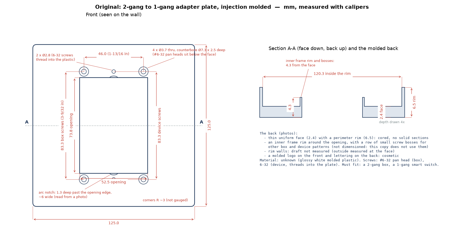
Its MEASURE.md keeps the hole spacings (NEMA standard), the hole and counterbore sizes and the
opening as critical and modeled as measured. The outline and depths are free; the 140 variant
makes them bigger. The molded back (a 2.4 mm face, a 6.5 mm rim, a cored inner frame with
extra screw bosses for other boxes) became a solid frame around the opening with straight ribs,
and the wall around each counterbore became 2.0 mm after the first print broke through a
0.05 mm skin there. Each of those rows says why.
b123d-print new plate --from plate_2gang_to_1gang
b123d-print spec plate